
If you’ve ever stared at a wall of framing details wondering what actually matters, this post will show you exactly how to read a framing plan—so you spot structural issues before they become inspection fails.
How to Read a Framing Plan Like an Inspector
Reading a set of construction plans isn’t just about seeing what’s drawn—it’s about understanding what’s really being communicated. That’s especially true with framing plans. These structural sheets tell the story of how loads are carried, transferred, and supported—from roof to ridge to foundation.

Whether you’re an inspector, builder, framer, or serious DIYer, this breakdown will help you look beyond the lines and start asking the right questions on-site.
If you haven’t already read my post on How to Read a Foundation Plan (So You Don’t Miss What’s Under Your Feet), start there first—because every load we’re about to talk about in this post depends on what’s happening down below.
Roof Framing Snapshot: What You’re Looking At

This plan excerpt shows a roof framed with conventional lumber using an 8:12 pitch—which means for every 12 inches of horizontal run, the roof rises 8 inches. That’s a pretty standard steep slope, offering good water runoff and attic space potential.
But what really matters is what’s beneath the surface:
- The rafter layout shows a clear ridge line at the peak, with uniform spacing.
- Bearing walls or beams must be verified below.
- Look for labeled framing like “2×10 rafters”.
- If you’re an inspector, you’re asking: Where is the load going? and What’s supporting this framing below?
Even though roof plans can look deceptively simple, your field inspection should never treat them like a ceiling tile layout. These are structural members—verify span, spacing, bearing points, and ventilation considerations.
Second Floor Detail: Dummy Rafters & Cathedral Ceiling
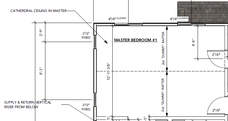
Zooming into Master Bedroom #1, the note reads: “Cathedral Ceiling in Master.” This means we’re not dealing with a flat ceiling under the attic—this ceiling is sloped and follows the roof line, often open to the peak.
But then you see something odd: “2×6 Dummy Rafter”… huh?
Here’s the scoop:
- ➤ These “dummy rafters” are not structural—they’re typically used to mirror the actual roof slope from below, helping maintain a consistent look inside the vaulted space.
- ➤ It’s common to see dummy rafters used as aesthetic or framing helpers during insulation and drywall install.
- ➤ Because there’s no ceiling joist tying the walls together, the roof framing (not shown here) must be supported with structural ridge beams or alternate methods (collar ties, engineered trusses, etc.)
Also worth noting:
- ➤ The windows are marked as “2/0 x 2/0 Fixed” – 2’x2′, which means they don’t open (no egress here).
- ➤ The glider doors on the top wall are noted as “4/0 / 4/0 GLIDERS” – 4’x4′(two panels, each approx. 2’ wide).
- ➤ As an inspector, always confirm framing coordination with actual window rough openings and header requirements.
First Floor Load Path: PSL Columns, Beams & Transfers

Knowing how to read a framing plan helps you avoid missed headers, skipped PSL’s and beams, or incorrect load transfers.
Identifying PSLs, LVLs, and Doubled-Up Members in a Framing Plan
As an inspector, one thing I always keep my eye on when reviewing framing details is engineered structural members—like LVLs (Laminated Veneer Lumber), PSLs (Parallel Strand Lumber), and double or triple-stacked dimensional lumber beams or posts. These aren’t just “bigger boards”—they’re structural red flags in the best way possible. Why? Because they usually signal either a concentrated point load or a significant span load that’s been calculated and placed intentionally by the design professional.
So, What’s an LVL?
An LVL (Laminated Veneer Lumber) is a type of engineered wood made by bonding thin layers of wood veneer together under heat and pressure. It’s incredibly strong along its length and used when a longer span or heavy load is involved—think supporting floor joists, roof loads, or carrying beams over large openings like garage doors.
And a PSL?
A PSL (Parallel Strand Lumber) is another type of engineered wood product, but instead of veneers, it uses long strands of wood fibers aligned and glued together under high pressure. PSLs are often used for columns/posts or heavy-duty beams where load transfer from above needs to be cleanly directed downward to a solid bearing point—like a foundation or structural footing.
Now let’s drop to the first floor and trace how those upper loads are being supported. In this Entry/Den view, it’s critical to spot the 3 1/2″ x 5 1/4″ PSL column tucked between the garage and the den.
What’s going on here?
- ➤ This PSL (Parallel Strand Lumber) post is carrying a concentrated load coming down from above.
- ➤ The architect started the structural load path from the second floor, where loads collect and direct weight down to this PSL.
- ➤ Then, we see (2) 1.75″ x 11.875″ LVLs landing directly on this PSL post—this is where the span load from the upper framing is being transferred.
- ➤ These LVLs don’t just hold up drywall—they’re engineered to transfer significant loads, especially over wide openings like the entry or large den spaces.
Always verify in the field:
- Is the PSL fully bearing top to bottom?
- Is any connection solid—Simpson connection hardware, Joist Hangers, etc.?
- Are fire separation details intact where this column intersects conditioned and garage space?
Field Tip from the Clipboard:
When I see PSLs, LVLs, or tripled-up 2x10s or 12’s on a plan, I know I’m looking at something important. That’s not overkill—it’s calculated. Whether it’s a roof truss bearing point, a second-story load-bearing wall above, or a flush beam carrying an open concept room, it’s telling you:
“Something significant is being carried here—make sure it’s going all the way down to the footing.”
This framing setup shows a textbook example of point load transfer done right—as long as all the connections and bearing points match the plan detail on site.
Garage Framing: Columns, LVLs & Fire-Rated Partitions
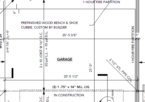
Finally, let’s pull up the garage plan and walk through what matters here structurally and code-wise.
Here’s what to focus on:
- ➤ The garage is framed with 2×10 joists @ 16” O.C., designed for 30 psf live load + 10 psf dead load.
- ➤ Supporting those joists are (3) 1.75” x 14” M.L. LVLs.
- ➤ These LVLs span across the full 20’+ garage width and are supported by 3 1/2″ steel pipe columns, aligning with known load points above.
More importantly:
- ➤ The “1 Hour Fire Partition” labels tell you this garage wall must meet IRC/IBC fire-separation requirements.
- ➤ This likely means Type X drywall, full height, sealed penetrations, and properly rated door assemblies.
- ➤ If this wall separates garage from habitable space, check for self-closing hardware and min 20-minute door rating at final inspection.
Fire separation in garages is a life safety measure, not just a drywall spec. As an inspector or contractor, always ask: Is this code-required fire barrier complete and intact all the way to the deck or roof sheathing above?
How to Read a Framing Detail: Watch the Full Walkthrough Here
If you want to see this exact post-to-beam detail broken down step-by-step, this video walks through how inspectors follow the load path, read the callouts, and spot the common mistakes that lead to red tags. Watch it here, then continue the guide below for the full written breakdown.
Final Takeaway: It’s Not Just Lines—It’s Load
When you look at structural sheets, the temptation is to skim for dimensions and move on. But these framing plans tell the load story—and whether you’re a framer or inspector, your job is to follow the load path:
- Roof → Wall → Beam → Post → Foundation/Footing
Miss one link, and the whole load path can fail.
So next time you’re standing on-site with a clipboard or drill in hand, slow down and ask:
“What’s really being supported here—and where is it going?”
Because reading plans isn’t about seeing ink on paper.
It’s about understanding the weight they carry.
If you’re looking to sharpen your eye for load paths, layout details, or just want framing tips you can actually use in the field…
👉 Check out this illustrated guide from APA – The Engineered Wood Association
This free PDF dives into advanced framing techniques like ladder blocking, single top plates, and load-aligned layouts. Great for builders, inspectors, and anyone who wants to frame smarter, not just stronger.