

IRC roof ventilation requirements aren’t just about adding vents—they’re a critical system to prevent moisture, heat damage, and premature roof failure.
This guide breaks down everything inspectors, contractors, and serious DIYers need to know about the 2021 IRC ventilation requirements (R806), what manufacturers expect, how to calculate Net Free Area (NFA), and what goes wrong when powered fans are added to passive vent systems.
Understanding IRC Roof Ventilation Requirements
R806.1 — Ventilation Required
Enclosed attics and enclosed rafter spaces formed where ceilings are applied directly to the underside of roof rafters must have cross ventilation for each separate space, unless the requirements for an unvented attic or unvented enclosed rafter assembly under R806.5 are met.
Required ventilation openings must open directly to the outside air and be protected against the entrance of rain or snow. They must also be protected to prevent the entry of birds, rodents, snakes, and other similar creatures.
Ventilation openings must have a least dimension of at least 1/16 inch and not more than 1/4 inch. Openings larger than 1/4 inch must be protected with corrosion-resistant wire cloth, hardware cloth, perforated vinyl, or similar material with openings between 1/16 inch and 1/4 inch.
R806.2 — Minimum Net Free Vent Area (NFA)
The standard minimum net free ventilating area is 1 square foot for every 150 square feet of vented space (1:150).
Exception — 1:300
The IRC permits the minimum net free ventilation area to be reduced to 1 square foot for every 300 square feet of vented space when both of the following conditions are met:
- In Climate Zones 6, 7, and 8, a Class I or II vapor retarder is installed on the warm-in-winter side of the ceiling.
- Not less than 40% and not more than 50% of the required ventilation is provided by ventilators located in the upper portion of the attic or rafter space. These upper ventilators must generally be located not more than 3 feet vertically below the ridge or highest point of the space. The balance of the required ventilation must be located in the bottom one-third of the attic space.
Where roof or wall framing prevents upper ventilators from being installed within 3 feet of the ridge or highest point, the IRC permits them to be located more than 3 feet below that point.
What Is a Ceiling Vapor Retarder?
For the 1:300 ventilation exception in Climate Zones 6, 7, and 8, IRC R806.2 requires a Class I or Class II vapor retarder on the warm-in-winter side of the ceiling.
Common examples can include:
- Class I: Polyethylene sheeting and other very low-permeance materials
- Class II: Kraft-faced fiberglass insulation and certain vapor-retarder coatings
The vapor-retarder requirement in R806.2 specifically applies to Climate Zones 6, 7, and 8. It is not a blanket requirement for using the 1:300 ventilation ratio in every climate zone.
R806.3 — Vent and Insulation Clearance
Where eave or cornice vents are installed, blocking, bridging, and insulation must not block the free flow of air.
IRC R806.3 requires at least a 1-inch space between the insulation and the roof sheathing and at the location of the vent.
This clearance maintains the required airflow path from the eave or cornice vent into the attic or rafter space.
Baffle Vent Requirements (Airflow Chutes)

The IRC addresses the required airflow clearance at eave and cornice vents in R806.3, while the specific requirement for eave baffles is found in N1102.2.3 (R402.2.3).
For air-permeable insulation in vented attics, a baffle must be installed adjacent to soffit and eave vents.
Code Summary:
- The baffle must maintain a net free area opening at least equal to the size of the vent.
- The baffle must extend over the top of the attic insulation.
- The baffle can be made of any solid material.
- The baffle must extend to the outer edge of the exterior wall top plate to provide maximum space for attic insulation over the top plate.
- Where soffit venting is not continuous, baffles must be installed continuously to prevent ventilation air within the eave soffit from bypassing the baffle.
- R806.3 separately requires at least a 1-inch space between the insulation and roof sheathing and at the location of the vent so insulation does not obstruct the free flow of air.
➤ Field Note: A soffit vent cannot provide the intended ventilation if insulation blocks the airflow path into the attic. The required vent opening, baffle, and clearance must work together to maintain an unobstructed path for ventilation air.
Manufacturer Requirements (GAF, Owens Corning, CertainTeed)
Roofing manufacturers provide their own ventilation requirements and installation instructions in addition to applicable code requirements.
Manufacturer guidance commonly emphasizes:
- Providing adequate intake and exhaust ventilation
- Maintaining a balanced ventilation system
- Avoiding multiple exhaust ventilation systems that can interfere with the intended airflow pattern
- Following the ventilation product manufacturer’s installation instructions and applicable roofing warranty requirements
➤ Manufacturer Note: Always verify the ventilation requirements for the specific roofing and ventilation products being installed. Requirements and warranty provisions vary by manufacturer and product.
Ventilation Calculation Example
Attic floor area: 1,200 sq. ft.
Using 1:300 ratio (where permitted by IRC R806.2)
- 1,200 ÷ 300 = 4 sq. ft. of total NFA
- 4 × 144 = 576 sq. in. NFA
- Split evenly: 288 sq. in. intake / 288 sq. in. exhaust
Option 1 — Ridge + Soffit Vents
- Soffit vents: 24 sq. in. each → 288 ÷ 24 = 12 vents
- Ridge vent: 18 sq. in./ft → 288 ÷ 18 = 16 linear ft
Option 2 — Slant-Back + Soffit Vents
- Slant-back vents: 60 sq. in. each → 288 ÷ 60 = 5 exhaust vents
- Still requires 288 sq. in. of soffit intake
Common Roof Vent Types
Ridge Vent
- Continuous exhaust along the ridge
- Commonly paired with soffit intake
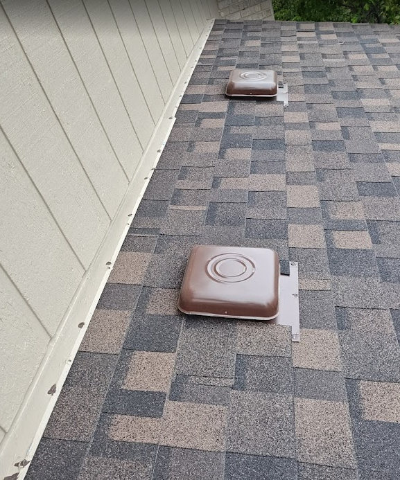
Slant-Back (Box) Vent
- Static exhaust vent
- Commonly used where ridge venting isn’t feasible
Gable Vent
- Provides ventilation through the gable wall
- Can interfere with intended ridge-and-soffit airflow patterns when ventilation systems are mixed
Soffit Vent (Rectangular)
- Provides intake ventilation at the eaves
- Must remain unobstructed
Continuous Soffit Vent
- Provides continuous intake ventilation along the eave
- Helps distribute intake air across the vented area
Turbine Vent
- Wind-driven exhaust ventilation
Powered Attic Fan
- Mechanically powered exhaust ventilation
- Typically controlled by temperature, humidity, or both
- Should not be combined with passive exhaust vents unless the ventilation system is specifically designed for that configuration
➤ NFA Note: Net Free Area varies by vent design and manufacturer. Use the manufacturer-rated NFA for the specific vent when calculating the required ventilation area.
Why Powered Attic Fans Can Undermine Ventilation
Powered fans are often installed to “help” vent the attic—but when mixed with passive exhaust vents such as ridge or slant-back vents, they can disrupt the intended airflow pattern.
Here’s what happens:
- The powered fan creates negative pressure in the attic
- Air can be drawn through nearby ridge, box, or other passive exhaust vents instead of through the intended soffit intake
- This can reverse the intended airflow through those passive vents
- The intended intake-to-exhaust ventilation pattern can be disrupted
➤ Avoid combining powered attic fans with passive exhaust vents such as ridge or box vents unless the ventilation system is specifically designed for that configuration.
Owens Corning Ventilation Calculator
If you want an excellent calculator to determine how much attic ventilation you really need check out this site and calculator by Owens Corning Roofing.
Final Takeaways

- Follow IRC R806.1–R806.3 for code compliance
- Use 1:150 unless the conditions for the 1:300 exception in IRC R806.2 are met
- Where required by N1102.2.3 (R402.2.3), install baffles adjacent to soffit and eave vents to maintain the required airflow path
- Match intake and exhaust NFA to avoid backdraft or reverse flow
- Avoid combining powered attic fans with passive exhaust vents unless the ventilation system is specifically designed for that configuration
➤ Real-World Insight: If the ventilation system does not provide the intended intake-to-exhaust airflow path, adding more vents or fans will not correct the underlying problem.