
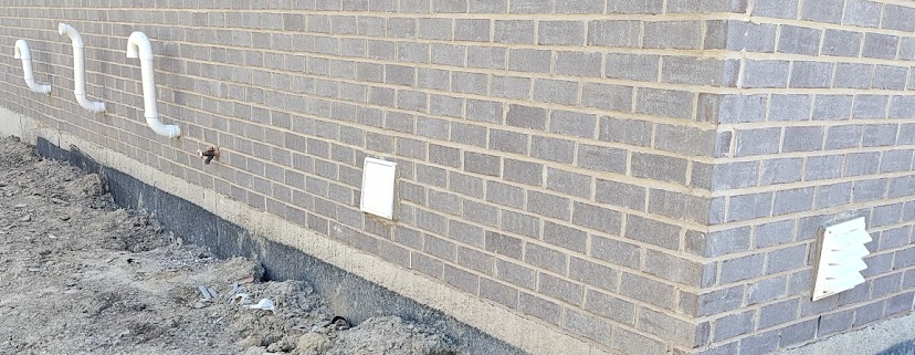
Two pipes or openings on the side of a house can look almost identical, but that doesn’t mean the same furnace vent clearance from air intake applies to every installation.
That’s where people get tripped up.
A furnace vent may terminate near an outdoor-air inlet serving the building, the combustion-air intake for another furnace or water heater, or a mechanical air-supply inlet. Before you grab the tape measure, you need to know what that opening actually serves.
Under the 2021 International Residential Code, those conditions are not all treated the same.
For through-the-wall vent terminals, the analysis starts with IRC Section G2427.8 (503.8), Venting System Terminal Clearances, and specifically Rows J and K of Table G2427.8.
The first question isn’t, “How far apart are these two openings?”
The first question is, “What kind of air inlet am I measuring to?”
Furnace Vent Clearance From Air Intake: What the 2021 IRC Says
Section G2427.8 addresses through-the-wall direct-vent and nondirect-vent terminal clearances through Figure G2427.8 and Table G2427.8.
For air inlets, two rows are especially important.
Row J — Nonmechanical Air-Supply Inlets and Other Appliances
Row J addresses clearance from the vent terminal to:
- A nonmechanical air-supply inlet to the building
- The combustion-air inlet to any other appliance
Here’s how to follow the table.
If you’re working under the 2021 IRC in the U.S. and your condition falls under Row J, find Row J in Table G2427.8. For a direct-vent terminal, Row J does not give you a separate clearance dimension. Instead, it tells you “Same as Row B.”
So your next step is to go to Row B.
Under the U.S. direct-vent column of Row B, the required clearance depends on the appliance input:
| Appliance Input | Minimum Clearance For Direct Vent Terminals |
|---|---|
| 10,000 Btu/h or less | 6 inches |
| More than 10,000 through 50,000 Btu/h | 9 inches |
| More than 50,000 through 150,000 Btu/h | 12 inches |
| More than 150,000 Btu/h | In accordance with the appliance manufacturer’s instructions, but not less than the clearance required for a nondirect-vent terminal |
What about a nondirect-vent terminal? Row J also directs you to Row B for that condition. Under the 2021 IRC U.S. requirements, a nondirect-vent terminal must be 4 feet below or to the side of the opening, or 1 foot above the opening. Check the applicable Row B requirements in the actual Table G2427.8 for the installation you’re evaluating.
So the code path is:
Air inlet condition → Row J → “Same as Item B” → Row B → identify whether the terminal is direct vent or nondirect vent → follow the applicable U.S. requirement.
That’s the part I want you to understand rather than simply pulling a clearance number from this article.
Use the actual table when applying the code. This article is based on the 2021 IRC. Verify the IRC edition adopted in your jurisdiction, check for local amendments, and then use the applicable version of Table G2427.8 to determine the required clearance.
Follow along with the official ICC Table G2427.8
I’ve covered Row B separately because it also addresses vent-terminal clearances to openings such as operable windows and doors. Here, we’re only using Row B because Row J specifically sends us there for the required clearance.
Row K — Mechanical Air-Supply Inlets
Row K addresses a different condition: a mechanical air-supply inlet.
Again, follow the table rather than assuming a clearance.
Once you’ve determined that the nearby opening is a mechanical air-supply inlet, go to Row K of Table G2427.8 and read across to the applicable column.
Under the 2021 IRC U.S. requirements, the vent terminal must be:
10 feet horizontally from the mechanical air-supply inlet or 3 feet above the inlet.
That’s a very different requirement from Row J.
And that’s why identifying the opening comes before measuring the clearance.
For the complete IRC figure and table, see the official ICC source:
2021 IRC G2427.8 — Venting System Terminal Clearances
Mechanical Versus Nonmechanical: What Does That Mean in the Field?
This distinction can be confusing because an air-supply inlet can include an automatically operated or motorized damper without the damper itself mechanically moving the air.
A good example is a passive makeup-air system. The 2021 IRC recognizes passive makeup-air systems and permits makeup-air dampers that automatically open when the exhaust system operates.
In that type of arrangement, the damper provides a means of opening and closing the air path. The presence of a motorized damper by itself does not mean that a fan or blower is mechanically supplying the outdoor air.
That’s why I wouldn’t classify an inlet as mechanical or nonmechanical based only on whether the damper is motorized. Identify how the air-supply system actually operates before deciding whether Row J or Row K applies.
Compare that with an air-supply or ventilation system where a fan or blower mechanically draws or supplies outdoor air through the inlet. The fan doesn’t have to be dedicated solely to the outdoor-air duct. For example, an outdoor-air duct connected to an HVAC system may use the furnace or air-handler blower to draw outdoor air through the inlet and then condition and distribute that air throughout the building. That is the type of mechanically supplied outdoor-air arrangement addressed by Row K.
By comparison, a kitchen exhaust hood can create negative pressure in the building and cause outdoor air to enter through a passive makeup-air opening. The hood fan is mechanical, but it is mechanically exhausting air from the building rather than mechanically supplying air through the makeup-air inlet.
So don’t classify an air-supply inlet simply by whether you see a motorized damper.
Ask how the outdoor air is actually being supplied through that inlet.
In simple terms:
Nonmechanical air-supply inlet → outdoor air enters without a fan or blower mechanically supplying it through the inlet.
Mechanical air-supply inlet → a fan or blower mechanically draws or supplies outdoor air through the inlet.
And there is one more condition that doesn’t require you to make that distinction.
If the opening is the combustion-air inlet for another appliance, such as another furnace or a direct-vent water heater, Row J specifically addresses that condition.
That’s where the analysis starts.
Another Furnace or Water Heater Changes the Analysis
Here’s a good field example.
Suppose you have a direct-vent furnace with its exhaust terminal on an exterior wall. A few feet away is another PVC pipe.
At first glance, somebody may assume it’s just another air intake and start looking at Row K.
Maybe. Maybe not.
If that pipe is the combustion-air inlet for another furnace, Row J specifically addresses it as the combustion-air inlet to another appliance.
The same applies if the nearby pipe is the combustion-air intake for a separate direct-vent water heater.
The fact that the other appliance may use a fan or inducer does not automatically move its combustion-air inlet into Row K. Row J specifically identifies the combustion-air inlet of another appliance.
That’s the language that controls the condition.
What About a Makeup-Air Inlet?
A makeup-air opening is another place where assumptions can cause trouble.
Don’t classify it by appearance alone.
A motorized damper can open a makeup-air duct without mechanically supplying the air. In that arrangement, the pressure difference created by the exhaust system may be what draws outdoor air through the opening.
On the other hand, a makeup-air system may use a fan or blower to mechanically draw or supply outdoor air through the inlet. That could be a separate makeup-air fan, or the system could use a furnace or air-handler blower to move the outdoor air as part of the HVAC system.
That’s why you need to determine how the particular system operates before deciding whether you’re looking at the nonmechanical air-supply inlet addressed by Row J or the mechanical air-supply inlet addressed by Row K.
The point isn’t to memorize what every exterior grille looks like.
The point is to identify the system first.
The Direct-Vent Exception Is Where People Get Tripped Up
Section G2427.8 includes an exception stating that the clearances in Table G2427.8 do not apply to the combustion-air intake of a direct-vent appliance.
Read too quickly, that can sound like combustion-air intakes are simply exempt from the table.
That’s too broad.
The exception matters when you’re looking at the relationship between a direct-vent appliance’s venting system and its own combustion-air intake.
For example, if you’re trying to determine the required separation between a furnace’s exhaust terminal and that same furnace’s combustion-air intake, Table G2427.8 is not where you establish that separation.
For that relationship, follow the listed appliance manufacturer’s installation instructions.
But now change one fact.
The furnace exhaust terminal is located near the combustion-air intake for another furnace or another appliance.
Row J specifically addresses the vent terminal’s clearance to the combustion-air inlet of any other appliance.
That’s a different condition.
If you’re trying to determine the separation between a direct-vent furnace’s own intake and exhaust terminations, I cover that separately in How Far Apart Should Furnace Intake and Exhaust Pipes Be?
Same Wall, Different Code Analysis
Consider three conditions on the same exterior wall.
Furnace Exhaust to Its Own Combustion-Air Intake
You have the exhaust and combustion-air intake serving the same direct-vent furnace.
Don’t use Row J to establish the separation between those two terminations.
Follow the appliance manufacturer’s installation instructions.
Furnace Exhaust to Another Appliance’s Combustion-Air Intake
Now the nearby intake serves a second furnace or a direct-vent water heater.
That’s no longer the furnace’s own combustion-air intake.
Row J specifically addresses the combustion-air inlet to another appliance.
From there, follow Row J’s direction to Item B. Because this example involves a direct-vent furnace terminal, read the applicable U.S. direct-vent requirement based on the appliance input.
Furnace Exhaust to a Mechanical Air-Supply Inlet
Now suppose the nearby opening is an outdoor-air inlet serving a mechanical supply system for the building.
That’s Row K.
Go to Row K of Table G2427.8 and read the applicable column. Under the 2021 IRC U.S. requirements, the vent terminal must be 10 feet horizontally from the inlet or 3 feet above the inlet.
Three openings may look similar from outside.
Three different analyses.
That’s why I wouldn’t approve or reject the installation based solely on what the pipes or grilles look like.
A Common Field Mistake
One of the easiest mistakes is seeing an intake near a furnace vent and immediately applying a clearance.
That’s backwards.
First identify the opening.
Is it:
- The combustion-air intake for the same direct-vent furnace?
- The combustion-air intake for another furnace?
- The combustion-air intake for a water heater or another appliance?
- A nonmechanical air-supply inlet to the building?
- A mechanical air-supply inlet?
Only after answering that question should you select the applicable row and measure the clearance.
Another common mistake is seeing the G2427.8 direct-vent combustion-air-intake exception and treating it as though every combustion-air intake is exempt from vent-terminal clearance requirements.
Row J is why that interpretation doesn’t work.
It specifically addresses the combustion-air inlet to any other appliance.
Questions to Ask Before Measuring
When you’re looking at a furnace vent near another exterior opening, work through it in this order:
- Which opening is the vent terminal?
- What does the nearby inlet serve?
- Is it the combustion-air intake for the same direct-vent appliance?
- Is it the combustion-air inlet for another appliance?
- Is it a nonmechanical air-supply inlet to the building?
- Is it a mechanical air-supply inlet?
- Does the G2427.8 exception change the analysis?
- What does the applicable Table G2427.8 actually require?
- What do the appliance manufacturer’s installation instructions require?
- Which IRC edition has the jurisdiction adopted, and has it been locally amended?
Once you know what you’re looking at, the table becomes much easier to apply.
Always Verify the Adopted Code and Actual Table
This article uses the 2021 International Residential Code to explain how G2427.8 and Table G2427.8 work.
Don’t assume that means the 2021 IRC requirements automatically apply to every installation.
Before applying a clearance in the field, verify:
- The IRC edition adopted by the jurisdiction
- Any state or local amendments
- The actual table in that adopted code
- The applicable U.S. column and vent type
- The appliance manufacturer’s installation instructions where applicable
The clearance numbers in this article are provided to help explain how to navigate the 2021 IRC table, not as a substitute for consulting the adopted code.
Follow along with the official ICC Table G2427.8:
2021 IRC G2427.8 — Venting System Terminal Clearances
Field Reminder
Identify the intake first. Find the applicable row. Then measure the clearance.
Get the Right Code Resource for the Job
Tired of code confusion, failed inspections, or second-guessing your work? Building Code Geek resources are written for contractors, inspectors, electricians, builders, permit applicants, architects, and serious DIYers. Every resource is practical, code-cited, inspection-tested, and designed to help you understand what the code actually requires.
Building Code Geek Guides
Pass the Inspection: A Field Guide to GFCI & AFCI Code Requirements
My book with clear explanations, real-world examples, diagrams, and field checklists to help you wire it right the first time and pass inspection with confidence. Covers NEC 2020 and 2023.
Building Code Geek Field Guides & Checklists
Browse the complete collection of downloadable field guides, checklists, bundles, and plan reading resources designed to simplify complex code requirements and help you get it right the first time.
Recommended Tools & Resources:
Trusted Tools & Resources for Contractors, Inspectors & Serious DIYers