

How to read a foundation plan is one of the most overlooked—but critical—skills for builders, inspectors, and DIYers alike. Before you frame a single wall, you’ve got to get this part right.
The footing and foundation section of the plans is where everything starts—and where things often start going wrong if you miss the details.
And we’re not just talking lines on paper here—this is the load path anchor for the entire structure.
It supports the roof, every floor, every wall, every beam—everything above it eventually pushes down through it. If that concrete isn’t the right strength, placed properly, or reinforced correctly? You’re looking at cracked walls, failed inspections, and worse.
So let’s walk it through using a real-world approved plan and learn how to read a foundation plan.

Double-Check Sheet Numbers First
This project plan set happened to contain two sheets labeled A-2.0. One is the correct foundation plan, and the other—although also marked A-2.0—is actually the First and Second Floor Construction Plans (per the sheet index).
Workaround: Always check the Sheet Index, not just the sheet number, since this duplicate numbering issue can happen during plan set exports.
We’ll be focused on the one titled:
“Foundation Plan, Notes, Details” (found in the sheet index on the cover sheet).
How to Read a Foundation Plan – Interpreting Real-World Details
Need a refresher?
As you can see, we’re referencing the cover sheet to locate the correct detail callouts throughout this post.
If you’re not sure how to find these sheet references—or want a better handle on how the whole set is organized—check out the first in the series, my Cover Sheet Walkthrough post and the matching YouTube video.
That’ll give you a solid foundation (pun intended) for navigating what comes next.
This foundation plan gives us:
- Layout for footings, walls, slabs, and porch
- Footing dimensions and location
- Slab thicknesses and notes
- Basement column pad/piers
- Reinforcement callouts (with detail links to Sheet A-4.0)
- Elevation detail tags and cross-references
Let’s break down the big stuff.
Footings: What’s Supporting What

From Detail 2/A-4.0, we get a standard continuous footing spec for exterior foundation walls:
- Size: 18 inches wide × 8 inches deep
- Rebar: (2) #5 horizontal bars min 3″ coverage
- Clearance: Bars must be supported off the soil using rebar chairs or dobies (not laid directly on trench soil)

Important field check:
The rebar needs to have at least 3 inches of clearance from soil when placed directly in contact with earth forms (IRC RR404.1, ACI Table 20.6.1.3.1a).
Also, per ACI standards and IRC, you are not allowed to pour into standing water.
If the footing trench looks like a soup bowl? That’s a red tag.
Concrete Notes on detail sheet A-2.0 include:
- The Mix Design: Must follow ACI 301 and the design professionals detail
- Concrete needs to achieve minimum 28 day compressive strength of 3,000 psi
- Forms shall remain in place until concrete hits 90% of 28-day strength
- All reinforcement/bars must be tied in place before the pour
Foundation Walls
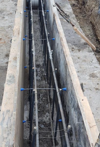
Detail 2/A-4.0 Includes:

- Wall Thickness: 10 inches
- Height: Varies depending on location—standard full-height wall for basement
- Reinforcement:
- (2) #5 horizontal bars top and bottom
- (1) #6 Vertical bars located 36″ O.C.
- (1) #4 Bar within 12″ of TOF and at 1/3 points based on wall height
✔️ Inspectors should confirm bars and spacing per design/IRC.
IRC R404.1.2 requires foundation walls to resist backfill pressure and carry vertical loads. Reinforcement spacing and wall thickness vary based on soil class—confirm if structural calculations were submitted or refer to default IRC tables.
Basement Piers / Column Pads

The plan shows (3) square piers/pads supporting steel columns in the basement. However:
- Exact dimensions are NOT noted on the plan.
- No label in the General Notes or in the details directly defines pier size.
Based on typical design for light residential loading and assuming medium soil bearing (3000 psf), these are likely 24″×24″×12″ thick, but do not assume—inspectors and contractors must confirm dimensions are specified in structural notes or by RFI to the architect/engineer.
Slab Details (Garage + Basement)
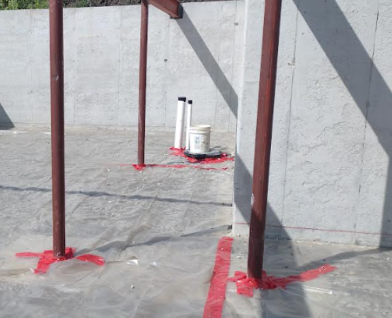
Basement Slab:
- 4″ concrete slab
- Reinforced with 6″ x 6″ W.W.F. (10/10 gauge)
- Installed over 6 mil polyethylene vapor barrier
- 4″ compacted stone base
- All joints must be sealed
Garage Slab:
- 5″ concrete slab, 4,000 psi strength
- Reinforced with 6″ x 6″ W.W.F. (10/10 gauge)
- Installed over 6 mil polyethylene vapor barrier
- 5″ compacted stone base
- Top of foundation depressed 10″ to accommodate slab
Inspector should confirm:
- Confirm crushed stone base is clean, well-compacted, and evenly graded—not loose fill or debris.
- Check that the poly vapor retarder is in place before the pour, seams are lapped and taped, and any pipe penetrations are sealed tightly.
- For residential work, see IRC Section R506.2.3 for minimum vapor retarder requirements
More on Vapor Barriers and the 10 Mil Code Shift:
Vapor Retarder Slab Code: Complete 10 Mil Rule & Sealing Tips – This post breaks down the IRC requirements, 10 mil best practices, and what to check during inspection.
Final Tips for Contractors & DIYers
Here’s your field cheat sheet:
- Footings match plan size?
- Reinforcement rebar/bars matches plan detail
- Bars tied in place and clear of soil? (Use dobies or plastic chairs)
- Vapor barrier installed under slab with proper lap seams and penetrations taped?
- WWF raised off poly ?
- No standing water in trench before pour – pump on site if raining?
- Cold/Hot-weather protection planned if needed?
- Pier pad sizes meet detail?
Miss one of these, and you’re not just risking a failed inspection—you’re rolling the dice on future structural movement.
🎥 Watch: How to Read a Foundation Plan (Walkthrough Video)
Prefer to see it in action? In this short video, I walk through a real foundation plan and explain exactly what matters for inspectors, contractors, and DIYers alike. From footing pads to stem wall notes—this quick field-style breakdown brings it all to life.
Conclusion
Footings and foundations aren’t just checkboxes—they’re the base of the entire house.
If you want everything above it to last? You’d better get what’s below grade done right.
This post showed you how to read the foundation plan and what those detail tags (like 1/A-4.0) really mean.
Want to really get fluent in plans? Catch the next installment of the Plan Reading Series.