
“What is the required bolt spacing for a deck ledger?”
Is one of the most common questions inspectors hear on deck framing inspections involves deck ledger bolt spacing requirements under the IRC.
Under the International Residential Code (IRC), there is no single universal spacing rule.
Ledger fastener spacing is determined by a prescriptive table in the IRC, and that spacing changes depending on several structural conditions.
Understanding how inspectors evaluate this connection requires looking directly at the governing section of the code.
Field Reality vs. Plan Review
In practice, smaller and straightforward deck projects can sometimes involve minor adjustments during construction. When conditions are simple and the change clearly complies with the IRC prescriptive requirements, an inspector may review the condition with the contractor in the field, verify that it meets the IRC provisions, and approve the adjustment with appropriate notation.
However, that situation should not replace proper planning. The most reliable approach is to submit deck plans that already meet the IRC prescriptive requirements—or an approved alternate design—and then construct the deck to match those approved plans. Field inspections are intended to verify that the work follows the approved documents, not to perform a full design review on site.
The Governing IRC Sections
Deck ledger connections to a house are addressed in:
IRC Section R507.9.1.3 — Ledger to band joist details
This section establishes the prescriptive method for fastening a deck ledger to a house band joist.
The requirements are defined through:
• Table R507.9.1.3(1) — Deck Ledger Connection to Band Joist (On-Center Spacing of Fasteners)
• Table R507.9.1.3(2) — Placement of Lag Screws and Bolts in Deck Ledgers and Band Joists
• Figure R507.9.1.3(1) — Placement of Lag Screws and Bolts in Ledgers
• Figure R507.9.1.3(2) — Placement of Lag Screws and Bolts in Band Joists
Section R507.9.1.3 also establishes a material requirement:
IRC R507.9.1.3 requires that fasteners used in deck ledger connections in accordance with Table R507.9.1.3(1) be either:
• hot-dipped galvanized, or
• stainless steel
and they must be installed in accordance with:
• Table R507.9.1.3(2)
• Figure R507.9.1.3(1)
• Figure R507.9.1.3(2)
What the Deck Ledger Fastener Table Actually Controls
The IRC does not prescribe one standard bolt spacing for deck ledgers.
Instead, Table R507.9.1.3(1) establishes the maximum on-center spacing of fasteners based on four factors:
• the design load category
• the deck joist span
• the type of fastener used
• the permitted sheathing condition between ledger and band joist
The table includes spacing values for:
• ½-inch lag screws with ½-inch maximum sheathing
• ½-inch bolts with ½-inch maximum sheathing
• ½-inch bolts with 1-inch maximum sheathing
Because the spacing varies depending on these conditions, the ledger fastener layout is typically established during plan review using the IRC table, and inspectors then verify in the field that the installation matches the approved plans.
There is no default prescriptive spacing allowed outside the table.
How Joist Span Affects Deck Ledger Bolt Spacing Requirements
One of the primary drivers of fastener spacing in the IRC table is deck joist span.
As joist span increases, the structural load carried by the ledger increases.
The IRC table accounts for this by reducing allowable fastener spacing as span increases.
For example, under 40 psf live load conditions:
| Joist Span | ½” D Lag Screws(½” sheathing) | ½” D Bolts (½” sheathing) | ½” D Bolts (1″ max. sheathing) |
|---|---|---|---|
| 6 ft | 30 in. | 36 in. | 36 in. |
| 12 ft | 15 in. | 29 in. | 24 in. |
| 18 ft | 10 in. | 19 in. | 16 in. |
Example values derived from IRC Table R507.9.1.3(1). Refer to the actual table for complete spacing requirements.
Inspectors reviewing a deck ledger typically determine:
- Deck joist span
- Fastener type
- Design load category
Those conditions are used during plan review to establish the required ledger fastener layout.
The installed spacing must not exceed the maximum spacing allowed by the table.
This becomes especially important on multi-level decks, where different deck levels can create varying joist spans and ledger loading conditions that must be accounted for during plan review.
Lag Screws vs Bolts Under the IRC
The IRC treats lag screws and bolts differently in the ledger connection table.
Separate columns are provided for:
• ½-inch lag screws
• ½-inch bolts
These fasteners behave differently structurally.
Lag screws rely on thread withdrawal resistance, while bolts function as through-bolted connections with nuts and washers.
Because of this difference, the allowable spacing values in the table are not identical.
During inspection, the fastener type installed should match the fastener type specified on the approved plans.
Sheathing Conditions in the Ledger Connection Table
The ledger connection table also accounts for the material located between the ledger and the band joist.
Two permitted conditions appear in the table:
½-inch maximum sheathing
and
1-inch maximum sheathing (for bolt installations)
The code footnotes further clarify permitted materials.
For the ½-inch sheathing condition, the sheathing must be:
• wood structural panel, or
• solid sawn lumber
For the 1-inch maximum sheathing condition used with bolts, permitted materials include:
• wood structural panel
• gypsum board
• fiberboard
• lumber
• foam sheathing
The code also allows up to ½ inch of stacked washers to substitute for up to ½ inch of allowable sheathing thickness when used with wood structural panel or lumber sheathing.
Contractors must ensure the wall assembly matches one of the sheathing conditions assumed by the table as shown on the approved plans.
Edge Distance and Fastener Placement Requirements
Fastener placement is governed by Table R507.9.1.3(2).
This table establishes minimum distances for lag screws and bolts installed in both the ledger and the band joist.
Ledger placement requirements
Minimum distances are:
• 2 inches from the top edge
• ¾ inch from the bottom edge
• 2 inches from the ledger ends
• 1⅝ inches minimum row spacing
Band joist placement requirements
Minimum distances are:
• ¾ inch from the top edge
• 2 inches from the bottom edge
• 2 inches from ends
• 1⅝ inches minimum row spacing
These distances help prevent splitting and maintain structural capacity in the wood members.
If fasteners are installed closer than these minimum distances, the installation does not meet the prescriptive requirements of the IRC.
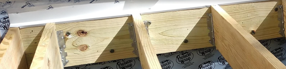
Stagger Pattern Requirements
The IRC also requires the fasteners to be installed in a staggered pattern.
This requirement is established in Table R507.9.1.3(2) footnote (a) and illustrated in:
Figure R507.9.1.3(1)
Fasteners must alternate between the upper and lower rows along the horizontal run of the ledger.
Installing all fasteners in a single horizontal line does not comply with the placement requirements shown in the figure.
Inspectors typically confirm the stagger pattern visually during inspection to ensure the fasteners alternate between the upper and lower rows as shown on the approved plans and required by the IRC or an approved alternate design.
Additional Code Requirements Affecting Ledger Fasteners
Several additional notes in Table R507.9.1.3(1) affect how the table is used.
Important provisions include:
• Interpolation is permitted; extrapolation is not permitted.
• Dead load is assumed to be 10 psf.
• Snow load shall not be assumed to act concurrently with live load.
• Lag screw tips must fully extend beyond the inside face of the band joist.
• Ledgers must be flashed in accordance with IRC Section R703.4 to prevent water from contacting the house band joist.
Each of these provisions affects how the prescriptive table can be used.
Engineered Rim Joists
Table R507.9.1.3(2) also includes a specific note regarding engineered framing.
When the ledger is attached to engineered rim joists, the code states:
The manufacturer’s recommendations shall govern.
In those cases, the installation must follow the manufacturer’s installation requirements, not just the IRC prescriptive table.
When the Prescriptive Ledger Table Cannot Be Used
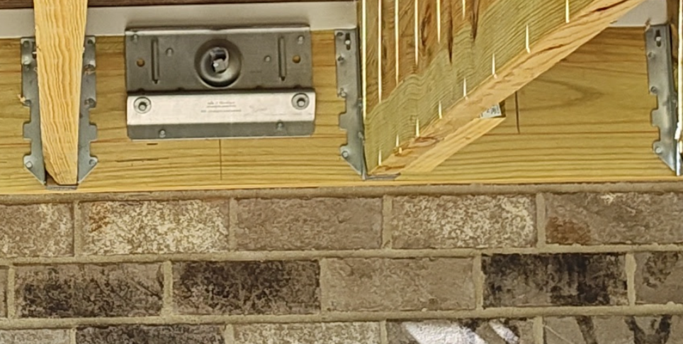
The prescriptive table applies specifically to ledger connections to a band joist, as indicated by:
Section title: Ledger to band joist details
Table title: Deck Ledger Connection to Band Joist
If the ledger connection does not match this prescriptive configuration, the fastener table cannot automatically be applied.
One common example is when a ledger is attached to brick veneer rather than a structural band joist. Brick veneer is not designed to support deck loads and these installations frequently fail inspection. See Why Deck Ledgers Attached to Brick Veneer Fail Inspection for a detailed explanation of this condition.
In those cases the IRC provides an alternative pathway.
IRC Section R507.9.1.4 — Alternate ledger details states that:
Alternate framing configurations supporting a ledger constructed to meet the load requirements of Section R301.5 are permitted.
In other words, when the installation does not match the prescriptive ledger-to-band-joist condition, the connection must still be capable of supporting the required structural loads.
How that support is provided will depend on the framing configuration used and must meet the load requirements of IRC Section R301.5.
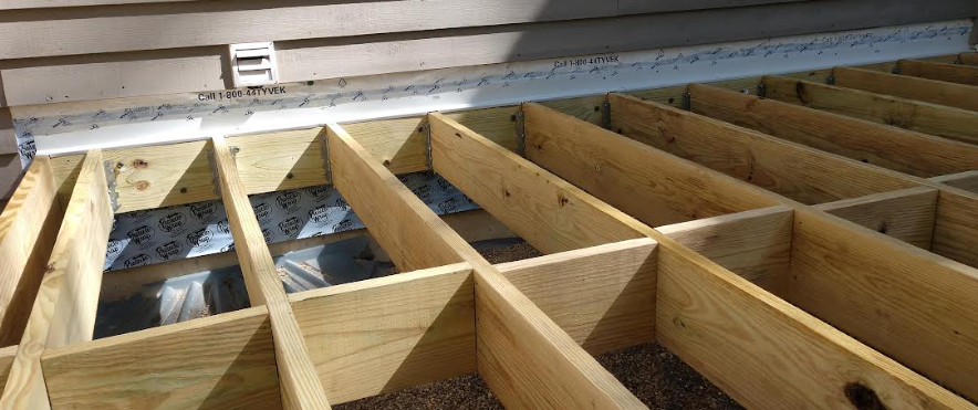
How Inspectors Evaluate Deck Ledger Fasteners
In practice, inspectors typically evaluate a ledger connection by confirming that the installation generally matches the approved plans and complies with the applicable IRC provisions.
- The ledger is attached to the house band joist as shown on the approved plans
- The fastener type matches the approved plans
- Fastener spacing generally matches the approved layout
- Fasteners are installed in the required stagger pattern
- Minimum edge distances and placement requirements are maintained
- Corrosion-resistant fasteners are used
- Ledger flashing is installed in accordance with IRC Section R703.4
If those conditions align with the prescriptive provisions of the IRC, the ledger connection complies with the code.
Final Inspection Takeaway
The key point is straightforward:
Deck ledger bolt spacing is not a fixed rule in the IRC.
Spacing is determined by the prescriptive table in IRC Table R507.9.1.3(1) based on:
• joist span
• load category
• fastener type
• permitted sheathing condition
Inspectors do not rely on common field spacing such as 16 inches or 24 inches on center.
Instead, they verify that the installation matches the approved plans, which should reflect the spacing determined from the IRC table.
Get the Right Code Guide for the Job
Tired of code confusion, inspection fails, or second-guessing your wiring? These practical field guides and checklists are built for pros, contractors, and serious DIYers—clear, code-cited, and inspection-tested. Grab the resource that fits your next project:
Available Guides:
• Pass the Inspection: A Field Guide to GFCI & AFCI Code Requirements
My book with clear explanations, diagrams, and field checklists to help you wire right the first time and pass every inspection. Covers NEC 2020/2023, written for real-world job sites.
• Kitchen GFCI & AFCI Requirements Checklist (NEC 2020 & 2023 Field Guide)
• Laundry Area GFCI & AFCI Requirements Checklist (2020 & 2023 NEC)